The Hardware Scaling Guide: Low Volume CNC Machining for Robot Joints
In the development cycle of dynamic robotic systems—whether building an autonomous mobile manipulator, a dynamic legged robot, or a multi-axis surgical wrist—engineering teams face an inevitable hurdle: the hardware "pilot gap."
Initial functional mockups with additive manufacturing (FDM, SLA, or SLS) serve well for cable routing and preliminary packaging checks. However, programs soon progress to a pilot batch of 10 to 100 units intended for closed-loop trajectory optimization, dynamic impact validation, accelerated life testing (ALT), and compliance trials. At this milestone, structural components must deliver genuine production-grade fatigue thresholds, strict isotropic stiffness, and dependable thermal paths.
Committing substantial capital to die casting dies or injection molding tooling is premature when joint gear ratios, encoder mounts, and bearing seats are still undergoing design optimization.
This is where low volume cnc machining for robot joints serves as an essential manufacturing strategy. It allows mechatronics developers to produce 10 to 500 sets of complex actuator housings, harmonic drive mounting cups, and link knuckles from wrought aerospace alloys with single-setup bearing fits—without locking in tooling capital or slowing down iteration speed.
- Modular Actuators: Why Dynamic Robot Joints Demand Billet CNC
Modern quadruped actuators, collaborative robots, and humanoid limbs rely heavily on quasi-direct drive (QDD) actuators or integrated smart modular joints. These assemblies integrate a frameless brushless DC (BLDC) motor stator, high-resolution absolute magnetic or optical encoders, a cross-roller bearing, and a precision reducer (strain wave or cycloidal gearhead) within a compact envelope.
Eliminating Dynamic Deflection Under Reversing Torque Spikes During rapid robotic trajectory reversals or dynamic emergency stops (E-stops), motor pinions deliver peak torque pulses to gear reducers in milliseconds. When joint housings are printed from sintered metal, anisotropic layer orientations and micro-porosity reduce shear strength and lower the dynamic elastic modulus. Under sustained cyclic reversing moments, micro-flex in printed joint housings leads to gear misalignment, localized tooth chipping, and accelerated spline fatigue.
Subtractive CNC machining carves joint knuckles directly from solid, wrought aerospace billets. Sourcing pilot-batch runs through an established precision CNC machining service guarantees complete structural density, uniform isotropic modulus, and the predictable dynamic stiffness required for precise trajectory control algorithms.
Sub-Micron Bearing Alignments and Runout Control
In an integrated robotic joint, the concentricity between the motor stator bore, the rotor shaft bearing journals, and the gearhead flexspline mounting pilot must remain within 0.005 mm to 0.010 mm. Even a 12-micron runout causes uneven gear tooth engagement, generating audible vibration, excessive operating temperatures, and harmonic torque ripple.
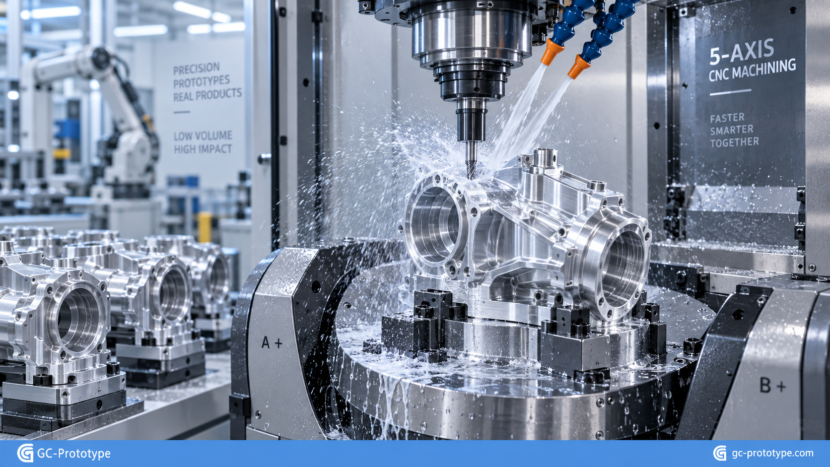
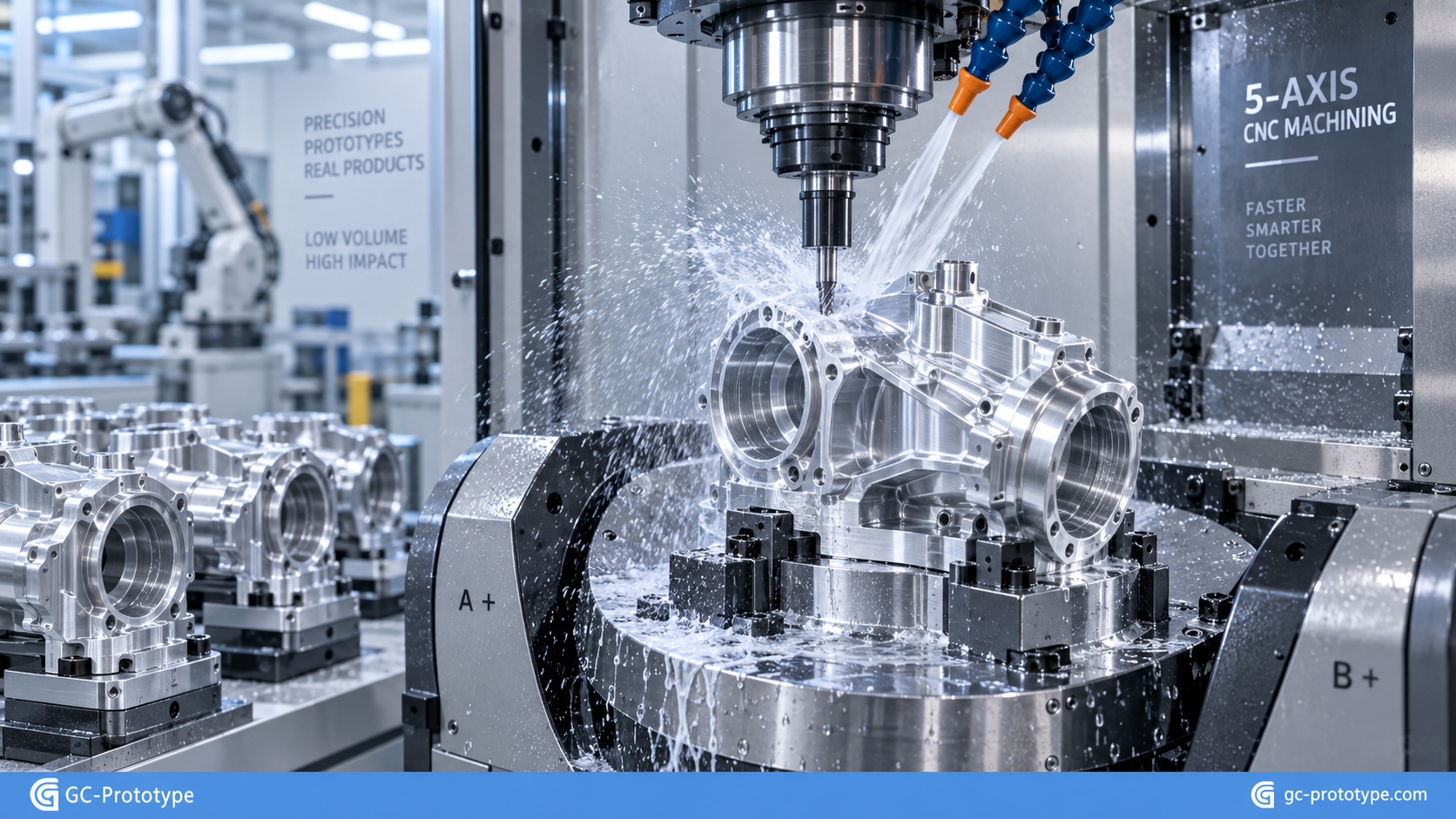
Low-volume 5-axis CNC machining centers finish critical bearing pockets, dowel locating holes, and encoder alignment lands in a single clamping setup, preserving geometric concentricity and perpendicularity across dozens of production sets.
Material Selection Matrix for Robot Joints
Selecting the optimal alloy requires balancing moving inertia, structural rigidity, thermal dissipation, and machining cycle times:
Aluminum 6061-T6: The Thermal Workhorse
For outer actuator housings containing frameless stator windings, 6061-T6 is the standard choice. It machines rapidly with minimal tool wear, easily accepts Type II anodizing or Type III hardcoating, and features high thermal conductivity (167 W/m·K). The machined housing acts as an active heat sink, drawing resistive thermal energy away from motor windings and onboard motor driver electronics.
Aluminum 7075-T6: Maximum Specific Strength for Knuckle Forks
Where robot limbs experience extreme bending moments—such as hip pitch or shoulder tilt joints—7075-T6 provides nearly double the yield strength of 6061. This high strength-to-weight ratio allows engineers to optimize structural wall thicknesses down to 1.2 mm while preventing permanent plastic deformation under shock overloads.
Precipitation-Hardening Stainless Steels (17-4 PH)
For output shafts, gear interface adapters, and keyed dowel couplings subjected to high torsional shear, 17-4 PH stainless steel offers high yield strength combined with moderate corrosion resistance. It can be machined in the annealed state and heat-treated with minimal dimensional distortion.
Reviewing a comprehensive CNC machining guide helps clarify toolpath strategies, spindle feed rates, and depth-of-cut trade-offs across different alloy classes.
DFM Rules to Lower Pilot-Run Production Costs
When scaling from one-off prototypes to batches of 20 to 100 units, programming overhead and raw cycle time drive per-part costs. Applying these Design for Manufacturability (DFM) rules shortens cycle times and reduces tool wear:
Internal Radii Sizing for High-Speed End Mills
End mills are rotating cylinders and cannot produce sharp 90-degree internal vertical walls.
The Pitfall: Specifying sharp inside corners forces machine shops to introduce sinker or wire EDM steps, increasing lead times and piece-part costs.
The Fix: Size interior vertical fillets at least 15% to 20% larger than the cutter radius (for example, use a 3.5 mm radius for a 6 mm end mill). This allows the tool to glide through corners continuously without decelerating, suppressing chatter marks and preventing tool deflection.
Standardizing Fasteners and Tap Depths Across Assemblies
Robot joints feature mounting patterns for frameless motor stators, bearing retaining rings, position sensors, and service covers.
Limit thread varieties to standard metric sizes (such as M2.5, M3, and M4 socket head cap screws) across the assembly to minimize automatic tool changes (ATC).
Restrict thread depth to 2 to 2.5 times the nominal diameter. Threading deeper adds no mechanical holding strength in aluminum alloys and increases the risk of tap breakage in blind holes.
Integrating Multi-Process Turn-Mill Capabilities
Actuator output shafts, planetary carrier plates, and strain wave wave generator hubs require tight rotational concentricity. Machining cylindrical geometries on a standard 3-axis mill introduces runout errors and requires multiple setups.
Utilizing dedicated custom CNC turning services equipped with live-tooling lathes allows parts to undergo OD turning, thread cutting, cross-hole drilling, and keyway milling in a single clamping cycle, maintaining coaxial alignment within 5 microns.
Quality Control, GD&T, and Batch Metrology Protocols
Consistent dynamic performance across a batch of 20 or 50 robot joints depends on repeatable kinematic datum structures and reliable metrology:
Assembly-Driven Datums: Establish primary datum (A) on the precision-faced mating flange, and secondary datums (B and C) on precision dowel holes. This ties CNC machining coordinates directly to kinematic joint rotation centerlines.
True Position Tolerancing: Use true position callouts for bolt circles and dowel locating holes to eliminate compounding tolerance stack-up across multi-link robot assemblies.
Batch Metrology Reports: For low-volume production runs, implement First Article Inspection (FAI) combined with Coordinate Measuring Machine (CMM) dimensional verification for critical bearing journals, dowel alignments, and gearbox centerlines before parts ship.
Accelerating Your Hardware Scaling
Bridging the gap between initial prototyping and volume production requires rapid manufacturing partners who understand precision robotic tolerances. By incorporating practical DFM rules—optimizing internal fillets, standardizing fastener threads, selecting high-conductivity alloys, and adopting live-tooling turning centers—engineering teams can cut pilot-run costs and turnaround times significantly.
When transitioning your modular actuator designs, cobot arm knuckles, or mobile manipulator chassis into pilot-stage production, partnering with an experienced manufacturing team like GC-Prototype ensures your designs receive thorough DFM analysis, tight-tolerance verification, and dependable factory-direct delivery.