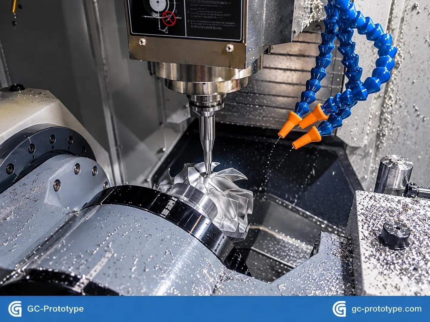
In modern hardware engineering, software development cycles iterate in hours, while physical hardware development often grinds to a halt waiting for custom metal and plastic parts.
Every mechanical engineer, roboticist, and mechatronic product designer reaches the same critical development fork: your bench is covered in 3D-printed SLA or FDM mockups, your CAD model is locked in SolidWorks or Fusion 360, and your embedded firmware is ready for dynamic testing. However, your mechanism requires high-torque motor housings that conduct heat away from drive stators, fluidic manifolds that hold pressure without weeping, or sub-micron bearing bores that will not deform under dynamic vibration. Additive plastics have reached their physical limits.
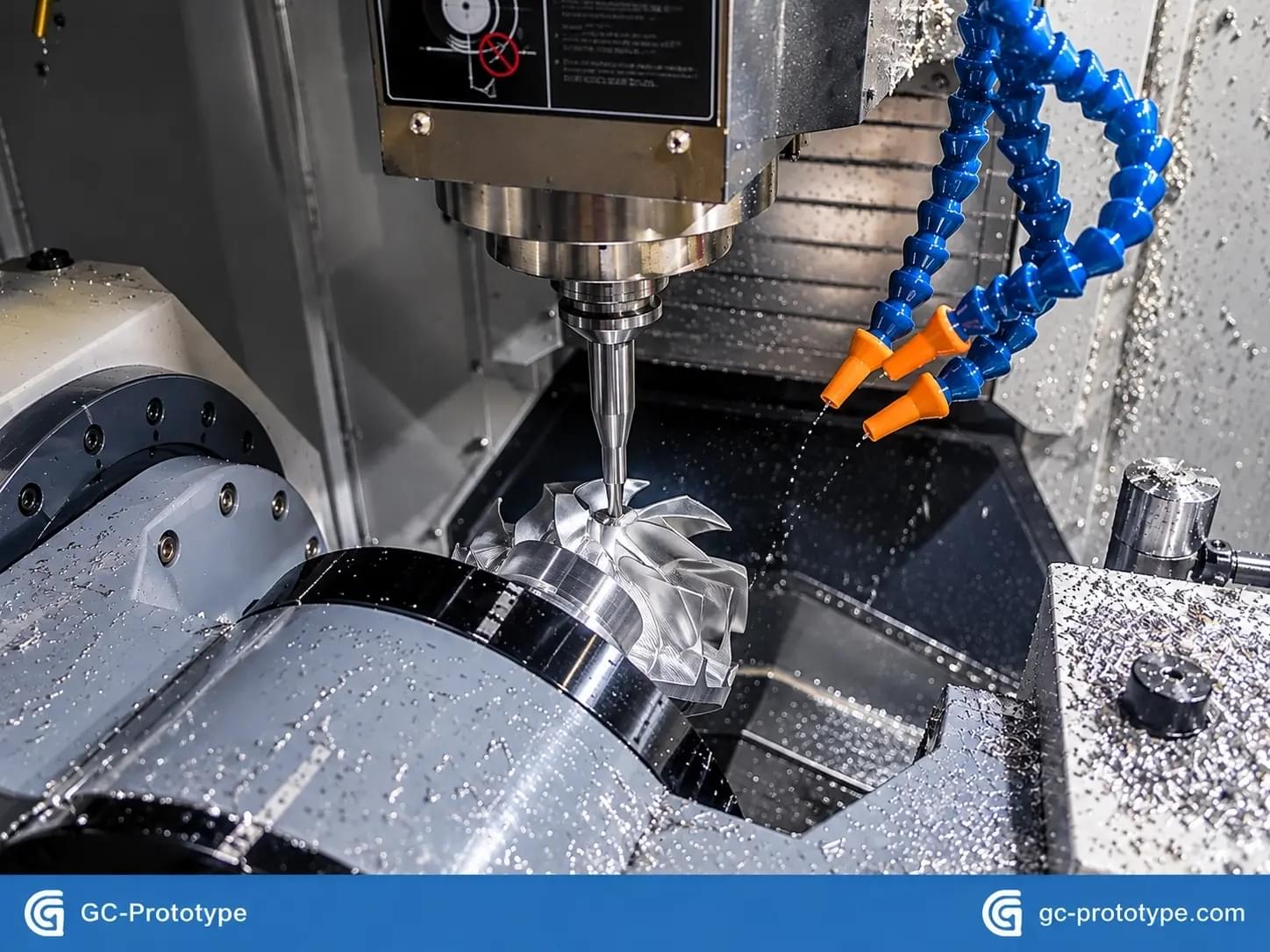
To build functional proof-of-concept units, mechanical test benches, and pre-series pilot assemblies, you must partner with an agile, high-precision prototyping machine shop Yet, treating a rapid prototyping shop like a standard high-volume production machine shop is one of the most expensive mistakes engineering teams make. Production facilities prioritize steady-state cycle-second optimization, hard tooling jigs, and high minimum order quantities (MOQs). In contrast, an agile prototyping shop specializes in high-mix, low-volume (HMLV) fabrication, rapid CAM setups, and aggressive turnarounds.
Below is an engineering analysis detailing how to evaluate a prototyping shop, optimize CAD files for fast-turnaround CNC workflows, select optimal materials, and assemble an RFQ package that eliminates engineering delays.
- Why Dedicated Prototyping Machine Shops Accelerate Hardware Sprints
Traditional CNC machine shops thrive on long-term predictability. Once a 4-axis horizontal milling center is dialed in with specialized hydraulic fixtures to churn out 50,000 automotive steering knuckles, interruptions are cost-prohibitive. Requesting a one-off motor bracket or three revision iterations from a volume factory often leads to prohibitive minimum charges and month-long lead times.
A specialized prototyping machine shop operates on an entirely different workflow:
Zero Minimum Order Quantities (Zero MOQ): Prototyping shops are engineered to fabricate 1, 5, or 20 sample units without requiring volume commitments.
Agile Modular Fixturing: Instead of manufacturing complex, dedicated hydraulic clamping jigs, prototype machinists utilize multi-axis dovetail clamps, vacuum chucks, and machinable soft jaws to complete multi-sided parts in fewer setups.
Active Design for Manufacturability (DFM) Collaboration: Rather than rejecting a print due to an unmachinable feature, a dedicated prototype engineering team reviews your STEP files, points out deep internal radii or non-standard tapped threads, and suggests geometry tweaks that save cycle time before cutting begins.
Partnering with an agile precision CNC machining service allows engineering teams to validate physical hardware iterations in parallel with firmware development.
- Core Machining Capabilities to Look For
When vetting a machine shop for functional prototyping, verify that their floor equipment supports multi-axis setups and diverse materials:
5-Axis Simultaneous CNC Machining
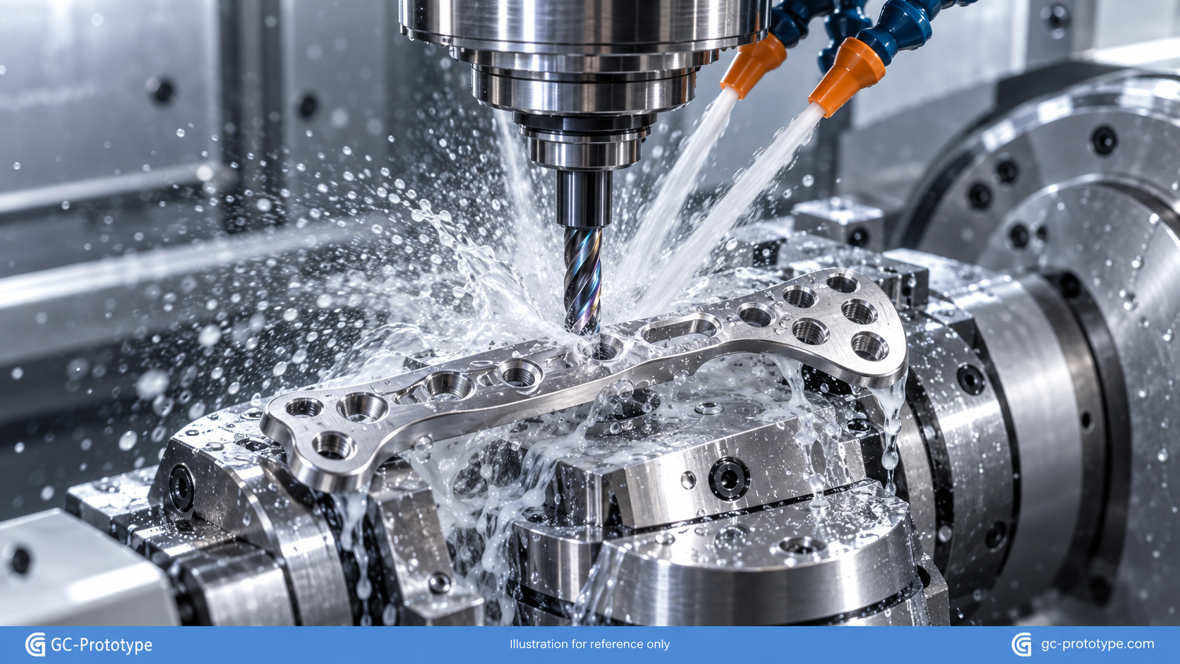
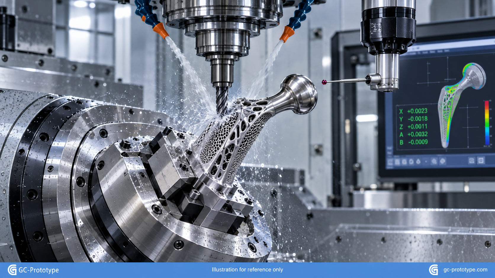
Traditional 3-axis mills require parts to be flipped manually across multiple setups to machine features on different sides. Each manual reclamping introduces cumulative datum errors and extends turnaround time. Simultaneous 5-axis machining allows the cutter to access five faces of a component in a single continuous clamping, ensuring tight geometric position and perpendicularity tolerances down to ±0.005 mm on robotic knuckles, drone arms, and complex impeller housings.
Multi-Tasking Turn-Mill Centers
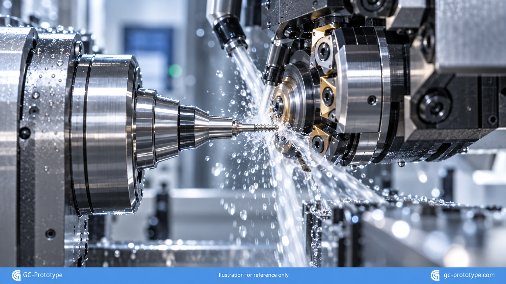
Parts such as drive shafts, fluidic manifolds, and planetary gear carriers combine cylindrical profiles with off-axis cross-holes, keyways, and external flats. Sourcing turned parts through dedicated custom CNC turning services equipped with live driven tooling allows turning and milling operations to finish on a single machine, eliminating spindle runout errors between separate operations.
Rapid Post-Processing Capabilities
Functional prototypes frequently require protective or functional surface finishes. A capable shop should manage media bead blasting, chemical passivation (for stainless and titanium), clear or color anodizing, and laser engraving in-house or through fast-track certified vendors to avoid shipping delays.
Consulting an authoritative CNC machining guide helps clarify spindle kinematics, tool clearance angles, and feed calculations across diverse machining centers.
Practical DFM Rules to Accelerate Prototype Delivery
Machining lead times and piece costs are heavily dictated by how easily cutting tools can access CAD features. Following practical Design for Manufacturability (DFM) rules prevents delays and lowers prototype costs:
Rule 1: Radius All Internal Vertical Corners
End mills are rotating cylinders. They cannot machine sharp 90-degree internal vertical walls.
The Problem: Designing sharp inside vertical corners forces machinists to set up secondary electrical discharge machining (EDM) operations, adding days to production and driving up costs.
The Solution: Specify internal corner radii that are at least 10% to 15% larger than standard cutting tool radii (e.g., specifying a 3.5 mm radius for a 6 mm end mill). This allows the tool to sweep smoothly through transitions without dwelling, preventing tool chatter and tool deflection.
Rule 2: Limit Blind Tap Depths
The Rule: Limit tapped thread engagement to 1.5 to 2 times the nominal fastener diameter (e.g., an M4 screw requires 6 to 8 mm of usable thread depth).
The Mechanical Reality: Threading deeper into aluminum or steel yields zero measurable increase in pull-out resistance, but drastically multiplies the risk of tap breakage in blind holes.
Rule 3: Maintain Wall Thickness Above Minimum Thresholds
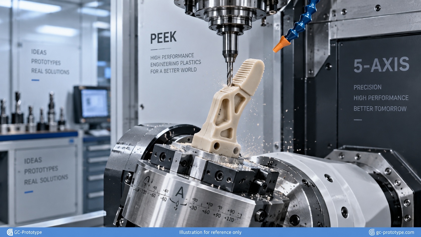
Plastics and thin metals deflect under tool cutting pressures. Maintain structural wall thicknesses above 0.8 mm for aluminum and 1.5 mm for engineering plastics (such as Delrin or PEEK) to prevent tool chatter, tapering, and part distortion.
- Prototype Material Matrix: Balancing Performance and Speed Selecting the correct raw stock balances prototype turnaround time, weight, and mechanical properties:
Aluminum 6061-T6: The universal baseline for hardware prototyping. It cuts cleanly, dissipates heat effectively, and is readily available in bar, plate, and tube stock.
Delrin (Acetal): The premier engineering plastic for prototypes. It produces clean chips without melting, holds dimensional tolerances easily, and provides natural lubricity for sliding mechanisms.
Aluminum 7075-T6: Ideal when 6061 fails finite element stress simulations but low component mass remains mandatory.
- How to Package the Perfect RFQ to Avoid Delays
When handing your designs off to a prototyping machine shop, how you format your manufacturing package directly impacts how fast the parts can be quoted and cut:
Provide Both 3D STEP and 2D PDF Files: Machinists use 3D STEP files to generate CAM toolpaths. However, they rely on 2D engineering drawings (PDFs) to identify tapped threads, reamed pin bores, surface roughness (Ra), and critical GD&T datums.
Avoid "Over-Tolerancing" Everything: Specifying ±0.005 mm across an entire title block forces the shop to run slow finish passes and conduct time-consuming CMM inspections on non-critical mounting brackets. Use general title block tolerances (±0.1 mm) for non-critical features, and selectively call out tight tolerances only where bearings, dowels, or dynamic seals interact.
Accelerating Your Physical Product Launches
Hardware development does not have to be slow. By understanding how a modern prototyping machine shop operates, designing parts for subtractive cutter kinematics, and preparing complete digital manufacturing packages, engineering teams can turn CAD concepts into functional metal hardware in days rather than weeks.
When preparing CAD files and technical drawings for your next robotics mechanism, industrial enclosure, or medical prototype, collaborating with an agile rapid manufacturing partner like [GC-Prototype] ensures your designs receive thorough DFM engineering reviews, micron-level precision, and dependable factory-direct delivery.
Comments
Join the discussionNo comments yet. Be the first to comment.